
One of the issues I foresee with my goal of building a computer from logic gates is coming up with a solution for outputting video from that computer to the screen. In this post I’ll discuss how I used a micro-controller to send some very basic images to an analog television using composite video signals. It may be helpful to refer to my previous post Electronic Basics: Circuit Components, however I’ll try to explain everything without having to rely too much on that. This is the another type of post that I’d like to have on my blog in addition to my technical posts and interesting/fun application posts where it’s more documenting my tinkering/experiments.
Raster Scanning
Raster scanning is the process by which most common television and monitors display image. This works by scanning across the screen line by line. After a horizontal line has been scanned, the television will then be moved down one line until it reaches the end of the screen. At the end of the screen, the TV starts scanning again from the top left. In the United States, a standard definition composite television has 525 horizontal lines per frame and scans at a rate of 63.555 microseconds per line. This gives an effective framerate of 29.97 frames per second. This was 30 frames per second before color television however, in order to fit color information in the signal without causing artifacts on the screen, the framerate was changed to 29.97.

Source: http://scanftree.com/computer-graphics/
The signal
The most important part of this whole exercise was figuring out what information needs to be in a composite video signal in order to display a picture. The signal itself conveys two important pieces of information: it tells the TV how bright the point it’s currently drawing should be and when the TV should start the next horizontal line and frame. In order to accomplish this, the signal is split into two parts. First a 0 volt sync signal is sent for either 4.7 µS to tell the tv to move to the next horizontal line (called a horizontal sync or H-sync) or 58.855 µS to tell the TV to start at the top for the next frame (called a vertical sync or V-sync). The rest of the time after the H-sync signal can then be used to transmit the video information with voltages from 0.3 representing black to 1.0 representing white. This gives me enough information to work with in generating my own video signals.

Actually doing it
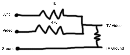
Leaning this, I felt as though I had enough to get hands on and try out my hand and generating some video signals. To do this, I used my Arduino microcontroller and a simple resistor network so I can drop the voltage of the Arduino signals to 1 volt to send to the TV, shown below. For the TV, I found a dinky radio television for about 5 bucks at a thrift store that needed a bit of modification in order to get working. This blog post was very helpful in actually getting this to work.
The Arduino first sets the sync and video signals to 0 for the required amount of time depending on whether it needs to do a V-sync or H-sync. It then sets the sync signal to 1 and video signals to 0 or 1 for the rest of the time to draw the image. Unfortunately, this setup only allows me to generate black or white and no greys.
The television needed a bit of modification in that its composite video port wasn’t a standard one so it wouldn’t work with the composite cable I had on-hand. In order to get around this I opened it up, took off the jack, and added some jumper wires. Some pictures showing the modifications are shown below.
Warning: Do not perform electrical work on CRT televisions unless you know what you’re doing. Capacitors within can be charged up to several hundred volts and the CRT itself to several thousand. I took many precautions to ensure all capacitors and the tube were fully discharged before I started working.


The Result

After several hours of tinkering, I was finally able to generate what could be called an image. A very basic face that seems none too thrilled to be a part of this escapade. I still have a bit to go in terms of how to draw images as currently I have to hard code each line but I certainly have a better grasp of video signals for when I’ll need to use them in the future.
Like and Follow if you enjoyed the read!

This is very cool, especially modifying the TV and coding video signals!
LikeLiked by 1 person